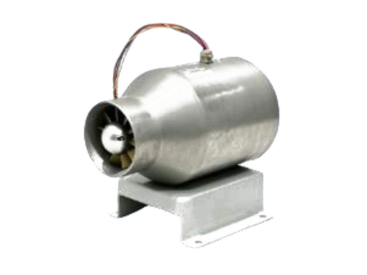
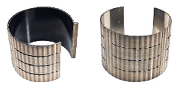
Air foil bearing
An air foil bearing carries the rotor, eliminating oil circuits and rolling elements at the source of friction, vibration and maintenance.
AIR FOIL BEARINGCORE TECHNOLOGY
The hard part of a high-speed air foil blower is not reaching a high speed. It is making the bearing, motor, impeller and control system work as one physical system. Our four core technologies address exactly that.
The bearing sets life and cleanliness, the high-speed motor sets the efficiency ceiling, the 3D impeller sets aerodynamic performance, and system integration determines whether they all work together in the real world.
An air foil bearing carries the rotor, eliminating oil circuits and rolling elements at the source of friction, vibration and maintenance.
AIR FOIL BEARING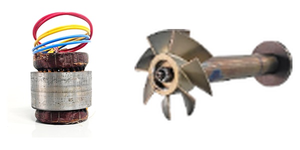
High efficiency, high power density and high temperature capability for continuous operation at 30,000–78,000 rpm.
HIGH-SPEED PM MOTOR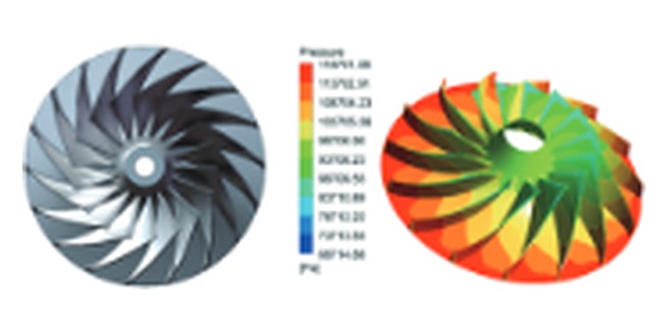
CFD iterations on blade angles and flow passages balance pressure ratio, wide operating range and low noise.
3D IMPELLER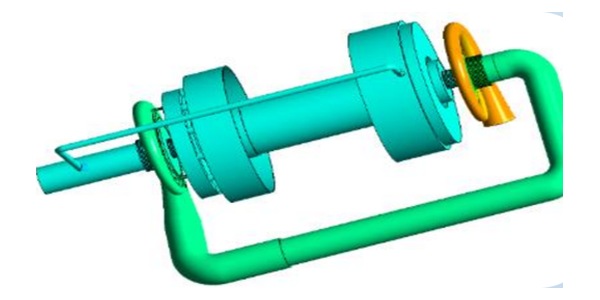
Multi-physics simulation balances mechanical, aerodynamic, electromagnetic, thermal and vibration behaviour at the complete-machine level.
SYSTEM COUPLINGHow the air foil bearing carries the rotor, how the impeller is designed and how the complete machine is matched — these are the reasons an air foil blower can save energy for years, not just on a datasheet.

At operating speed, air is drawn into the wedge between the foil pads and the shaft, creating a hydrodynamic support that lifts the rotor. In normal operation, metal no longer touches metal, so no oil is required and there is no rolling-bearing wear.
During start-up and shutdown, the wear coating on the foil surface carries brief contact. This is why coating material, foil geometry and assembly precision matter so much in an air foil bearing.
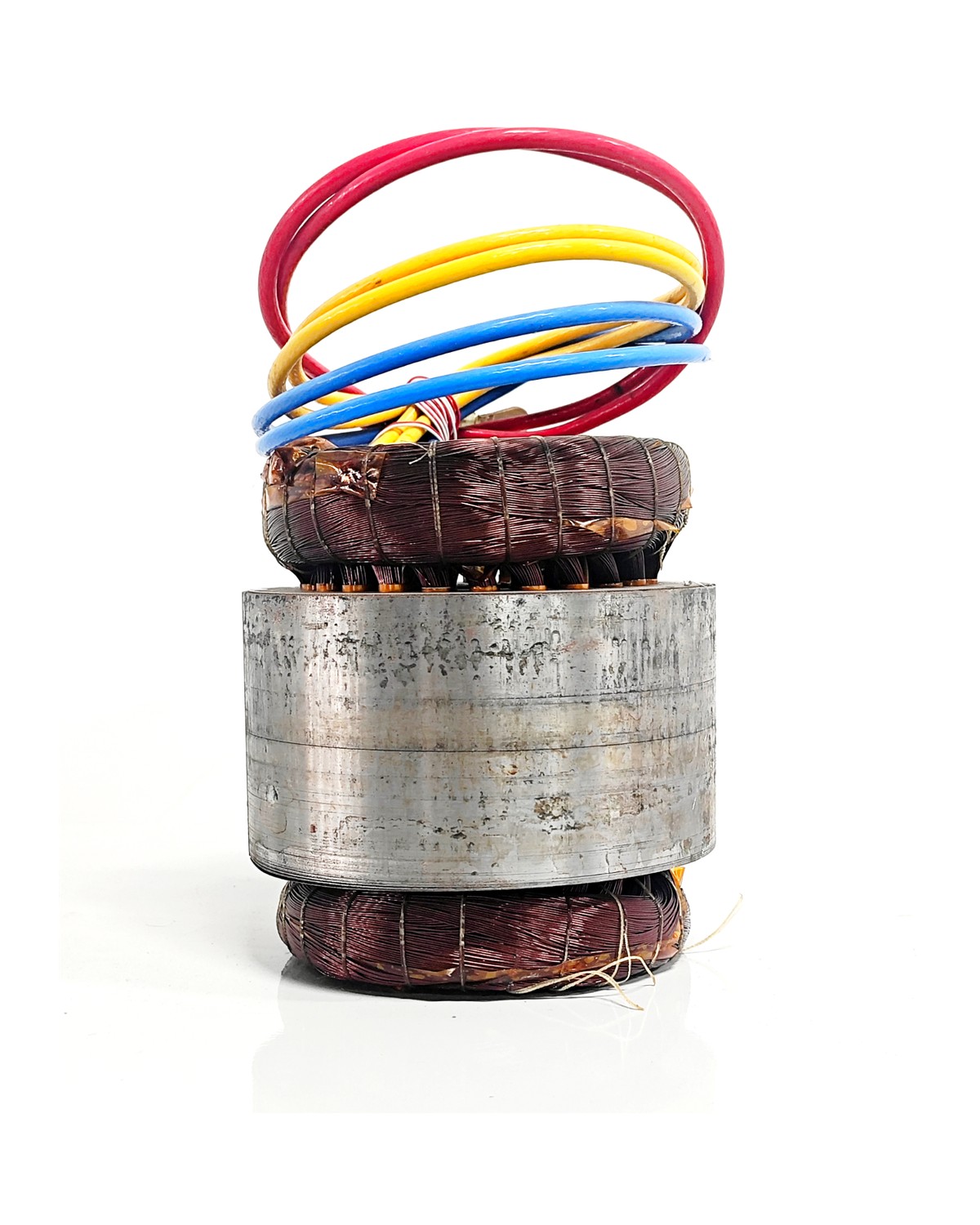 FIG. 02 — HIGH-SPEED PM MOTOR
A high-speed air foil blower needs a motor that is equally light, fast and heat-tolerant. LANFENG uses a high-speed permanent-magnet synchronous motor platform with a titanium rotor and embedded samarium-cobalt magnets, achieving high strength, low weight and high temperature capability. A high-frequency drive converts electrical energy more directly into shaft power.
 FIG. 03 — 3D IMPELLER
The impeller is the heart of aerodynamic efficiency. Using three-dimensional CFD, we balance flow, pressure, efficiency and noise: inlet and outlet blade angles, passage curvature and diffusion are adjusted to reduce separation and secondary flow, so more of the shaft power becomes useful air.
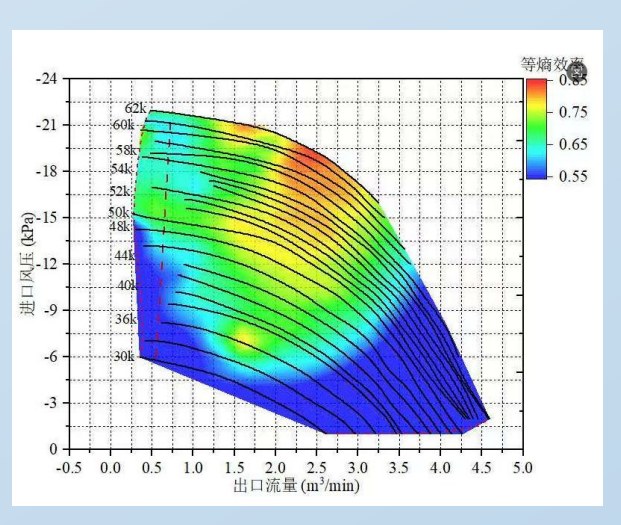 FIG. 04 — CFD / SYSTEM COUPLING
A bearing, a motor and an impeller can each be excellent and still fight each other when assembled. System coupling puts mechanical structure, aerodynamics, heat, electromagnetics and vibration into one model, searching for a system-level balance instead of adding four “good parts” together.
From components to the complete machine, key performance is verified before dispatch. We prefer test data to adjectives.
Rotor and impeller imbalance is controlled to reduce vibration and bearing load at speed.
01 / BALANCINGSpeed, pressure, flow, current and vibration are checked on the test stand.
02 / FULL-SPEED TESTTemperature rise and noise are recorded at key operating points for site assessment.
03 / THERMAL & NOISECritical-process records and final inspection support repeatable, traceable delivery.
04 / CONSISTENCYTest scope and acceptance criteria depend on model, order requirements and applicable standards.
TECHNICAL DISCUSSION
Replacing scroll blowers, redesigning pipework or specifying a high-temperature or vacuum model — start with a concrete process conversation.